- [email protected]
- +86-21-63353309
cheek plate design
cheek plate design
PadEye Calculator (shackle compatibility & design capacity

Fig 2 shows the limiting stresses to be considered when designing a padeye. Bearing stress is distributed across the main plate and the cheek plates.
Learn MoreCLARK: CHEEK PLATE Cheek plate (reverse), with eagle design and the

Download CLARK: CHEEK PLATE Cheek plate (reverse), with eagle design and the motto 'The Spirit of Seventy-six,' on the butt of a rifle belonging to Am
Learn MoreC series jaw crushers Wear parts application guide

piece jaw die design. A 1 piece jaw design is now also designed for large crushers (C110, C120, C125, C140, and C160). Upper cheek plate Lower cheek plate Movable jaw Fixed jaw 6 5 4 3 2 1 0. 10 Accessories Intermediate plate An intermediate plate can be used when feed capacity is low (empty cavity), feed size
Learn MoreOPTIMUM ANALYSIS OF OFFSHORE STRUCTURES LIFTING

Padeye design and analysis plays an important roles during the lifting, load out and installation of heavy structures. This study addressed the different dynamic The effective thickness of the cheek plate can be increased to 100% with proper fabrication and welding sequence. Finite Element analysis is a good tool to have better
Learn MoreLifting Lug Design | MecaLug Software - Meca Enterprises

MecaLug Standard version is the least expensive version of the software that allows the user to perform Padeye / lifting lug calculations per ASME BTM-1 “Design of Below-the-Hook Lifting
Learn MoreLASHING PADEYE DESIGN - SpreadsheetConverter

diameter of cheek plate, d, = mm. thickness of cheek plate, t, = mm. distance pin outer to shackle, H, = mm. Jaw Width of shackle, B, =
Learn MorePadeye Design Cheek.xls

Discipline: Calc'd by:TITLE: LOCATION:DESIGN OF PADEYE USING CHEEK PLATES Bottom of Spreader BeamReference:Rev C
Learn MoreLift Design with cheek plate

Lift Design - With Cheek Plate 1- IMPUT: 1.1 - WORK LOAD: Qc = 0.800 tf 1.2 - IMPACT LOAD: I = 1.25 1.3 - NUMBER OF SLINGS: Nc = 2.0 cable(s) 1.4 - SLING
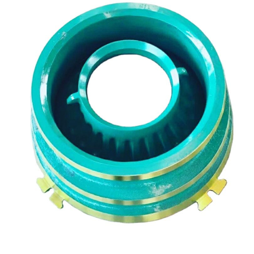
Learn MoreCheek Plate - Sandrock Mining
We can provide customized design according to our clients’ requirement and also refine our products by our clients’ feedback. Available Models for Jaw Crusher Parts CJ Series CJ211,CJ409,CJ411,CJ412,CJ612,CJ613,CJ615,CJ8115
Learn MoreTHORDSEN CUSTOMS | Thordsen Customs

AR-15 Gen III Stock Kits. FRS-15 Gen III 5.56/.223 Bundles (AR-15) FRS-15 Gen III .308 Bundles (AR-10) FRS-15 Gen III AK-47 Bundles; FRS-15 GEN III SIG SAUER Bundles
Learn MoreFlanges (Cheek Plates) - ULTRA TEC Manufacturing, Inc
for Precision Saws with 0.5 inch arbor (spindle). Flanges (Cheek Plates) are sold as a pair. They reduce the lateral wander of peripheral (OD) blades under
Learn MoreDesign of Padeye
designed as to permit free movement of the shackle and sling If fillet welded cheek plates are used to obtain the pad eye thickness required in 3.4.1
Learn MorePadeye Design Guidelines - Design & Manufacturing

For padeyes rated above 2000kg capacity cheek plates must be fitted to reduce the play in the shackle-padeye connection. These must be fitted as additional
Learn MoreUS5222886A - Cheek plate for a vane pump - Google Patents

It is an object of the present invention to design a cheek plate such that it can be manufactured at low cost. Specifically, fewer steps of manufacture are
Learn MoreWhy skewing is not beneficial for your HPGR - Outotec

Traditional cheek plates vs. flanged roll design #3 - Skewing helps to even pressure across the full width of the roll. All machines with static cheek plates are designed to control skewing via the hydraulic system. Pressure is reduced on the skewing side of the roll with the smaller grinding gap (distance between the two rolls) in order to
Learn MoreSteel Plate Design - Structural engineering general discussion - Eng-Tips

The tieback design loads were generally in the 200 to 400 kip range. The steel for the bearing plates had Fy = 50 ksi. The plate thickness for a 5-strand, 176 kip DL anchor was 2.75 inches. If you ask the tendon supplier, they will often give you the plate design for the particular anchor design load and span.
Learn MoreCLARK: CHEEK PLATE Cheek plate (obverse), with angel design, on the

Download CLARK: CHEEK PLATE Cheek plate (obverse), with angel design, on the butt of a rifle belonging to American soldier and explorer William Clark
Learn MorePadEye Calculator | shackle compatibility & capacity | CalQlata

1) Enter design load including factors ( F) 2) Select a shackle size from the 'SWL' list 3) Enter cheek-plate and pin-hole clearances ( C & Cᴾ) 4) Enter a maximum allowable stress for the padeye plate ( σ) 5) And a few other dimensions (cheek-plate thickness, Young's modulus and weld joint factor)
Learn Morejaw plates for cj412 | cheek plate design
ROTOR, 500 OPEN SIDED BARE cheek plate design red rhino crusher for sale HP5 TOOL ASSY HP400-500 HP5 used impact crusher for sale. All QMS jaw plates are stocked in 14%, 18% and 22% grades of manganese with a chrome content of 2-3%.
Learn MoreLifting Lug Design with example – What Is Piping

27/01/2022 · A Lifting lug is a plate with a hole in it. As the term specifies, lifting lugs are used for lifting. The hole is sized to fit a clevis pin. Using lifting lugs combined with the clevis pins, loads are transferred from one mechanical component to another. For mechanical static equipment (Fig. 1), these lifting lugs are used by cranes for
Learn MoreStandard padeye CAD drawing ready for cutting (dwg, dxf, pdf

Standard pad eye design suitable for lifting and seafastening applications. (8) Plate thickness as per drawing and padeye weight as table below
Learn MoreInquiry
Established in 1991, Our is a leading enterprise in the field of China’s mixing engineering machinery.
We possesses the fixed assets of over 190 million RMB, with over 1200 staff in total. We are an professional international company focusing on the development


- [email protected]
- +86-21-63353309
- +86-21-63353309
- No. 4529, Kangxin Highway, Pudong New District, Shanghai China